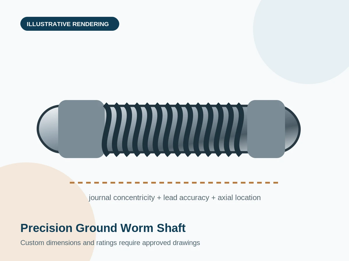
A precision ground worm shaft combines the worm tooth form and shaft journals in one component, making journal concentricity, axial location and tooth lead accuracy part of the same manufacturing problem. This product page is structured for RFQs that define the shaft by an approved drawing or sample, including the tooth system, starts, helix hand, lead angle, journal diameters, bearing seats, shoulders, keyways, thread ends, heat treatment, hardness and inspection requirements.
What should be defined before quotation?
A useful quotation starts with the geometry that controls mating and assembly. Provide the module or diametral pitch system, pressure angle or tooth profile standard, number of worm starts, wheel tooth count, ratio, helix hand, center distance, shaft angle, face width, bore and hub details, keyway or spline data, and the datum scheme used on the drawing. When an existing part is being replaced, a sample can help identify missing details, but the sample should not replace a dimensional drawing when interchangeability matters.
Operating data are equally important. State the input speed range, continuous and peak output torque, hours per day, starts per hour, reversing duty, shock events, ambient temperature, contamination, required holding behavior, lubrication method and maintenance interval. A gear set that is adequate for occasional manual adjustment may not be suitable for continuous conveying or repeated reversing. The sales drawing should therefore separate nominal operating values from short-duration peaks and emergency conditions.
Technical scope table
| Item | Required RFQ input | Status on this page |
|---|---|---|
| Gear system | Module/DP, profile, starts, helix hand, wheel teeth and ratio | Customer-defined |
| Installed geometry | Center distance, shaft angle, mounting datums and contact position | Customer-defined |
| Load and speed | Input rpm, continuous torque, peak torque, duty cycle and starts/hour | Not stated |
| Materials | Worm, wheel, hub and shaft material requirements | Engineering confirmation |
| Heat treatment | Process, case depth, hardness and areas excluded from treatment | Engineering confirmation |
| Accuracy and inspection | Applicable standard, grade, runout, lead, pitch and contact checks | Drawing-dependent |
| Lubrication and environment | Oil/grease, temperature, water, dust, washdown and corrosion exposure | Application-dependent |
| Quantity and documentation | Prototype/production quantity, reports, material traceability and packaging | Customer-defined |
Common engineering options
- Integral shaft or separate worm-on-shaft concept
- Single, double or multiple starts
- Through-hardened, carburized or induction-hardened concepts subject to review
- Ground tooth flanks where the tolerance and application justify it
- Black oxide, phosphate or corrosion-control finishes outside finished tooth zones
These are common industry concepts, not a statement that every combination is feasible. The final pairing should consider sliding velocity, heat generation, wear, lubrication, surface finish and the strength of both the tooth system and the supporting shafts or hubs. A material that performs well in one speed and lubrication regime may not be appropriate in another.
Load capacity, efficiency and holding behavior
Worm gearing combines rolling and sliding contact. Efficiency changes with lead angle, number of starts, input speed, surface finish, lubricant, bearing losses, run-in condition and assembly quality. For that reason, a single efficiency percentage should not be applied to every custom design. Thermal capacity can also become the governing limit in continuous duty even when the tooth strength appears adequate.
Self-locking should never be treated as an automatic safety feature. The ability of the wheel to back-drive the worm depends on geometry, friction, materials, lubrication, vibration, accuracy and bearing behavior. Where reverse motion could create a hazard or allow a suspended load to move, specify an independent brake, lock or safety mechanism and validate it at system level.
Installation and contact pattern
The worm and wheel must be installed at the intended shaft angle and center distance, with the worm centered across the wheel face according to the drawing datum. Worm gearing creates axial thrust, so the bearing arrangement and shaft retention must be designed for the direction of rotation and helix hand. A contact pattern concentrated on one edge often indicates alignment, center-distance, shaft-location or housing-deflection problems.
Before full-load operation, verify secure mounting, backlash, lubrication, shaft rotation and tooth contact. Run the assembly at reduced load while monitoring temperature, noise, vibration and oil condition. Stop the test if abnormal heating, binding, metal debris or unstable contact appears. Exposed gears require guarding and a lockout procedure for installation and maintenance.
Application context
This product family can be considered for metering drives, conveyor take-up mechanisms, gate and valve actuation, baler and feeder adjustments, positioning tables. Application references describe possible functional roles only. They do not imply compatibility with a specific machine model until the interfaces, duty data and safety requirements have been checked.
Key failure risks to review
- Runout between worm tooth reference and bearing journals
- Heat-treatment distortion not reflected in grinding allowance
- Undersized shaft shoulders for axial thrust retention
- Secondary machining in hardened tooth areas
- Incorrect helix hand or start count compared with the mating wheel
Wear is not controlled by tooth strength alone. Poor lubrication, contamination, misalignment, an unsuitable material pair or excessive sliding speed can damage the surface at a load below a nominal tooth-strength limit. Conversely, a conservative load with repeated shock, high starts per hour or a large overhung load may overstress shafts, bearings or the housing.
Drawing and sample approval
For build-to-print work, the approved drawing should control. Mark all critical-to-function dimensions, datums, tolerances, heat-treatment zones, hardness, surface finish, tooth data and inspection requirements. When reverse engineering a sample, identify which dimensions are measured, which are inferred and which remain unknown. Worn teeth can no longer represent the original backlash or profile, so the replacement design may require mating-part inspection or a new center-distance calculation.
Dimensional changes requested after heat treatment or tooth finishing can be difficult or unsafe, especially in hardened tooth zones. Confirm bores, keyways, shoulders, threads and mounting holes before the final process route is released. If the part is a matched set, both components should be identified and kept together through inspection and shipment.
Maintenance planning
Maintenance intervals should be based on lubricant condition, contamination, temperature, duty cycle and observed wear rather than on a universal hour value. Establish a baseline for backlash, operating temperature, noise and vibration after commissioning. Trend changes over time, inspect seals and breathers, keep abrasive dust away from open gearing, and protect stored components from corrosion. After a jam or overload, inspect tooth contact, shafts, keys and bearings before returning the machine to service.
RFQ checklist
- 2D drawing and 3D model if available
- Existing sample or clear photographs
- Module/DP, ratio, starts and helix hand
- Input speed and output torque
- Duty cycle, shock and starts per hour
- Material, heat treatment and hardness
- Backlash and accuracy requirement
- Lubrication and environmental conditions
- Prototype and annual quantities
- Inspection and documentation needs
Frequently asked questions
Can a worm and wheel be quoted separately?
Yes, but the mating data must be known. Provide the existing worm or wheel geometry, helix hand, starts, module or DP, center distance and backlash requirement. A separately quoted component cannot be assumed to mesh correctly with an unidentified mating part.
Can you guarantee self-locking?
No universal guarantee is appropriate from geometry alone. Holding behavior depends on friction, materials, lubricant, lead angle, speed, vibration and assembly. Use an independent brake or lock where reverse motion would be hazardous.
Can a worn sample be reverse engineered?
A sample can support identification, but wear may obscure the original profile, pitch and backlash. Critical geometry should be confirmed against the mating part, center distance and application duty.
What information is needed for an agricultural application?
Provide the machine function, crop or material handled, input power and speed, continuous and peak torque, jamming events, starts per hour, dust/water exposure, lubrication access and seasonal storage conditions.
Are the images product photographs?
No. The visuals are original illustrative engineering renderings created for page layout. They are not photographs, dimensional drawings or evidence of a finished production part.
When is a final drawing approved?
Approval should occur after the tooth data, interfaces, materials, heat treatment, tolerances, inspection requirements and order quantity have been reviewed. Production should follow the approved revision.
Request a review for Precision Ground Worm Shaft
Send drawings, tooth data, duty conditions, quantity and inspection requirements to [email protected].
Open RFQ page