Engineering guide
Worm Gear Selection Guide
Ratio, torque, speed, starts, helix hand, center distance, duty cycle and service factor for custom worm gear RFQs and design review.
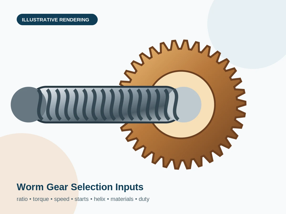
Ratio, torque, speed, starts, helix hand, center distance, duty cycle and service factor for custom worm gear RFQs and design review.
Start with input speed, output torque, peak torque, duty cycle, starts per hour and reversing. Ratio alone is not enough.
Module or DP, starts, helix hand, center distance, wheel teeth, pressure angle/profile and face width must be compatible.
Daily operating time, shock classification, starting frequency, ambient temperature and jamming events change the required margin.
Worm gears generate sliding friction. Efficiency and thermal capacity depend on lead angle, speed, lubricant, materials and assembly.
Axial thrust, overhung loads, shaft deflection, center distance and housing stiffness affect contact and life.
Do not rely on self-locking for safety. Use an independent brake or lock where needed.
General context derived from connected worm gear catalogues and current official standards information. Product-specific values must be calculated for the actual design.