Engineering guide
Worm Gear Installation and Alignment Guide
Shaft angle, center distance, tooth contact, thrust bearings, guards and startup checks for custom worm gear RFQs and design review.
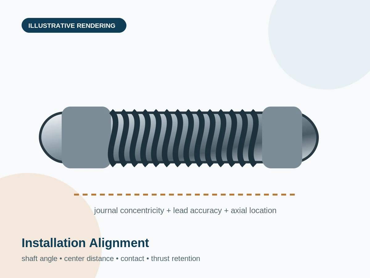
Shaft angle, center distance, tooth contact, thrust bearings, guards and startup checks for custom worm gear RFQs and design review.
Use the drawing datums for shaft angle, center distance and axial position. Do not center only by visual appearance.
Worm gearing generates axial thrust. Select bearings and shaft retention for both rotation directions if reversing.
Verify contact at low load. Edge contact suggests alignment, center-distance or housing-deflection issues.
Measure backlash under stated conditions and avoid zero-backlash assembly.
Confirm lubricant, guards, fasteners, free rotation, noise and temperature before applying full load.
Lock out power during installation and maintenance, and guard exposed rotating components.
General context derived from connected worm gear catalogues and current official standards information. Product-specific values must be calculated for the actual design.