Description
Worm gear reducer technology serves as the backbone for many precision motion control systems across global manufacturing sectors. The EP-NMRV series by Ever-Power provides a robust solution for engineers seeking to bridge the gap between high-speed motor inputs and controlled, high-torque mechanical outputs. By utilizing an aluminium worm gearbox design for smaller frames and heavy-duty cast iron housings for larger models, this equipment adapts to various environmental demands. Whether your facility requires compact integration or massive power handling, these units offer a predictable performance profile that minimizes downtime in critical production lines.
Selecting the right speed reduction component involves balancing spatial constraints with the necessary mechanical strength of the assembly. This model series excels by offering a wide range of gear ratios and input power capacities to suit diverse machinery requirements. From lightweight aluminium worm gearbox configurations for delicate tasks to the substantial iron bodies found in larger frame sizes, the versatility is unmatched. Buyers can rely on consistent engineering quality that facilitates smooth transitions in rotational speed while maintaining the structural integrity required for continuous industrial duty cycles in demanding markets.
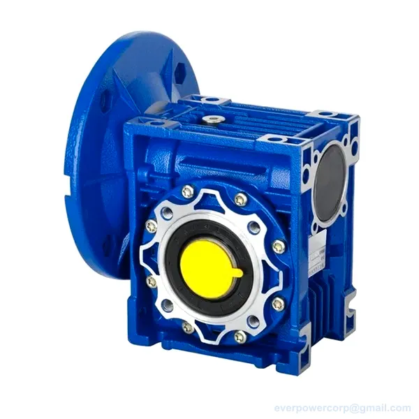
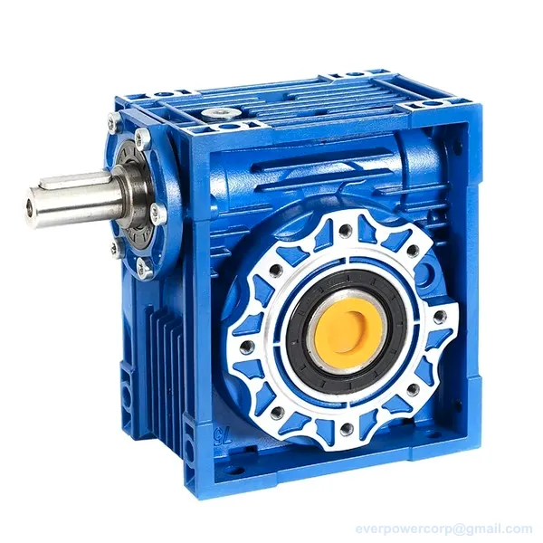
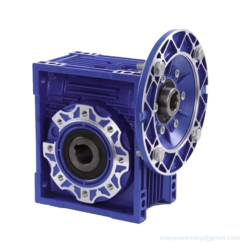
Product Snapshot – Worm Gearbox With IEC Motor Flange
Maximize operational efficiency by selecting a model that matches your required torque and speed profiles. Reduce installation complexity through versatile mounting options designed for diverse industrial environments. Ensure long-term durability with high-quality materials like the ZCuSn10Pb1 tin bronze worm wheel crown used in every frame size.
Key figures shown for NMRV worm gearbox.
- Rated input power (kW): 0.09~0.55
- Output speed at i=7.5, n1=1400 rpm (rpm): 187
- Output speed at i=100, n1=1400 rpm (rpm): 14
- Output torque at i=7.5, n1=1400 rpm (N·m): 41
- Output torque at i=100, n1=1400 rpm (N·m): 29
Specifications & Parameters – Worm Gear Speed Reducer
The specification table below covers the figures buyers ask about first. Available models include NMRV worm gearbox, worm gear speed reducer, aluminium worm gearbox. Read it alongside your load profile and production plan.
| Parameter | EP-NMRV040 | EP-NMRV050 | EP-NMRV063 | EP-NMRV075 | EP-NMRV110 | EP-NMRV130 |
|---|---|---|---|---|---|---|
| Centre distance (mm) | 40 | 50 | 63 | 75 | 110 | 130 |
| Gear ratio range (i) | 7.5~100 | 7.5~100 | 7.5~100 | 7.5~100 | 7.5~100 | 7.5~100 |
| Rated input power (kW) | 0.09~0.55 | 0.12~1.5 | 0.18~2.2 | 0.25~4.0 | 0.55~7.5 | 0.75~7.5 |
| Rated input speeds (rpm) | 900 / 1400 / 2800 | 900 / 1400 / 2800 | 900 / 1400 / 2800 | 900 / 1400 / 2800 | 900 / 1400 / 2800 | 900 / 1400 / 2800 |
| Output speed at i=7.5, n1=1400 rpm (rpm) | 187 | 187 | 187 | 187 | 187 | 187 |
| Output speed at i=100, n1=1400 rpm (rpm) | 14 | 14 | 14 | 14 | 14 | 14 |
| Output torque at i=7.5, n1=1400 rpm (N·m) | 41 | 77 | 130 | 235 | 532 | 780 |
| Output torque at i=100, n1=1400 rpm (N·m) | 29 | 52 | 94 | 206 | 473 | 765 |
| Efficiency at i=7.5, n1=1400 rpm (%) | 86 | 88 | 88 | 91 | 90 | 91 |
| Efficiency at i=100, n1=1400 rpm (%) | 48 | 48 | 49 | 63 | 63 | 66 |
| Weight (kg) | 2.3 | 3.5 | 6.2 | 9 | 35 | 48 |
| Housing material | Aluminium case and flanges, steel worm, bronze worm wheel crown | Aluminium case and flanges, steel worm, bronze worm wheel crown | Aluminium case and flanges, steel worm, bronze worm wheel crown | Aluminium case and flanges, steel worm, bronze worm wheel crown | Iron body and flanges, steel worm, bronze worm wheel crown | Grey cast iron G200, protective powder coating |
| Lubricant | Synthetic ISO VG 320 | Synthetic ISO VG 320 | Synthetic ISO VG 320 | Synthetic ISO VG 320 | Synthetic ISO VG 220 | Synthetic ISO VG 220 |
| Worm wheel material | ZCuSn10Pb1 tin bronze | ZCuSn10Pb1 tin bronze | ZCuSn10Pb1 tin bronze | ZCuSn10Pb1 tin bronze | ZCuSn10Pb1 tin bronze | ZCuSn10Pb1 tin bronze |
| Worm shaft material | 20CrMnTi, carburized and quenched | 20CrMnTi, carburized and quenched | 20CrMnTi, carburized and quenched | 20CrMnTi, carburized and quenched | 20CrMnTi, carburized and quenched | 20CrMnTi, carburized and quenched |
| Output shaft material | Steel 45# | Steel 45# | Steel 45# | Steel 45# | Steel 45# | Steel 45# |
| Input bore diameter (mm) | Φ9(Φ11,Φ14) | Φ11(Φ14,Φ19) | Φ14(Φ19,Φ24) | Φ14(Φ19,Φ24,Φ28) | Φ19(Φ24,Φ28,Φ38) | Φ24(Φ28,Φ38) |
| Input shaft diameter (mm) | Φ11 | Φ14 | Φ19 | Φ24 | Φ28 | Φ30 |
| Output bore diameter (mm) | Φ18(Φ19) | Φ25(Φ24) | Φ25(Φ28) | Φ28(Φ35) | Φ42 | Φ45 |
| Output shaft diameter (mm) | Φ18 | Φ25 | Φ25 | Φ28 | Φ42 | Φ45 |
| Mounting positions | B3, B6, B7, B8, V5, V6 | B3, B6, B7, B8, V5, V6 | B3, B6, B7, B8, V5, V6 | B3, B6, B7, B8, V5, V6 | B3, B6, B7, B8, V5, V6 | B3, B6, B7, B8, V5, V6 |
| IEC motor flange options | 56B14, 63B14, 63B5, 71B14, 80B14, etc | 56B14, 63B14, 63B5, 71B14, 80B14, etc | 56B14, 63B14, 63B5, 71B14, 80B14, etc | 56B14, 63B14, 63B5, 71B14, 80B14, etc | 56B14, 63B14, 63B5, 71B14, 80B14, etc | 56B14, 63B14, 63B5, 71B14, 80B14, etc |
Note: Figures can vary with configuration and operating conditions — confirm against the official technical drawings or with our team before ordering.
Reference Standards & Target Markets:
Target markets for this worm gear reducer line: United States, Germany, Brazil, Australia. Buyers in these markets can request dimensional drawings and the selection data behind the table above before placing an order.
Published engineering standards that apply to this product type. They are listed for selection reference — consult the source document for the authoritative text.
- ISO/TR 14521:2010 — Gears — Calculation of load capacity of wormgears. Specifies equations for calculating the load capacity of cylindrical worm gears, covering load ratings associated with wear, pitting, worm deflection, tooth breakage and temperature. Scuffing and other failure modes are not covered. Valid for tooth-surface sliding velocities up to 25 m/s and contact ratios of 2,1 or greater; dimensioning rules apply to centre distances of 50 mm and larger. Source
- ISO 1122-2:1999 — Vocabulary of gear terms — Part 2: Definitions related to worm gears geometry. Cited as a normative reference by ISO/TR 14521:2010; defines the geometry terminology used for worm gearing. Source
- ISO 701:1998 — International gear notations — Symbols for geometrical data. Cited as a normative reference by ISO/TR 14521:2010; fixes the symbols used for gear geometrical data. Source
Worm Gear Reducer Key Features – NMRV Worm Gearbox
Robust Material Construction
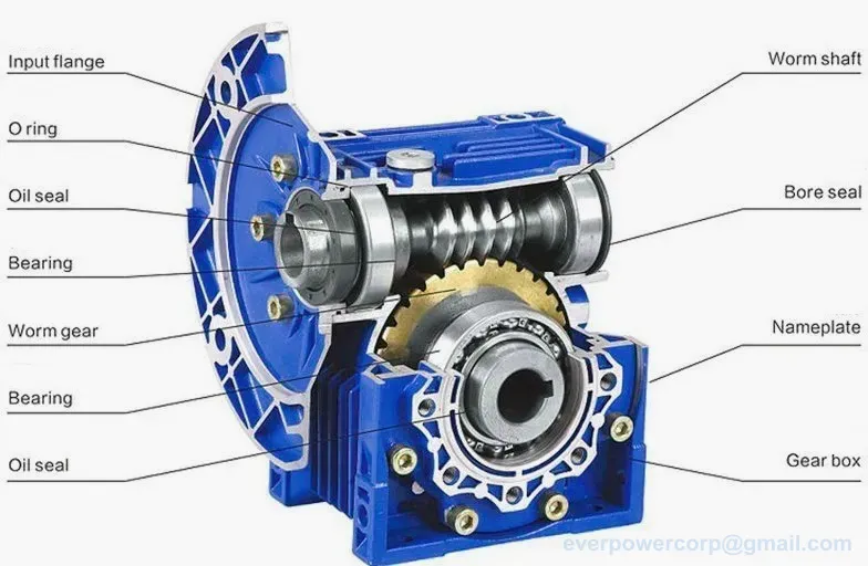
The internal architecture of this equipment is built to withstand significant mechanical stress over long periods. Each unit features a steel worm that has undergone carburizing and quenching processes to enhance surface hardness and fatigue resistance. The worm wheel crown is crafted from ZCuSn10Pb1 tin bronze, which provides an excellent balance of friction reduction and wear resistance. This combination of high-grade metals ensures that the internal components maintain their profile even under heavy loading conditions, preventing premature failure during intense operation.
Exceptional Running Quality
Smoothness in motion is a hallmark of this machine's design philosophy. By optimizing the contact between the worm and the wheel, the equipment achieves highly stable rotational output with minimal vibration. This stability is critical for applications where precise positioning or constant velocity is required to prevent product damage. The precision-machined internal components work in harmony to reduce noise levels, making these units suitable for environments where acoustic comfort and mechanical smoothness are prioritized by operators.
High Mechanical Efficiency
Energy conservation is integrated into the very core of this model through advanced geometry. The design focuses on maximizing the power transfer from the input shaft to the output shaft while minimizing parasitic losses. Higher efficiency ratings mean that less heat is generated during the reduction process, which in turn protects the internal lubricants and seals from thermal degradation. This efficient energy conversion helps reduce overall operational costs for industrial facilities looking to optimize their power consumption patterns.
Compact And Serviceable Design
Space optimization is essential in modern automated production lines, and this equipment addresses this need through its streamlined form factor. The housing is designed to be compact without sacrificing the strength needed for high-torque applications. Furthermore, the accessibility of the unit allows for straightforward inspection and maintenance tasks. This serviceability ensures that technicians can quickly perform routine checks or lubrication updates, reducing the time required for scheduled downtime and keeping production schedules on track.
Versatile Configuration Options
Every industrial setup is unique, which is why this series offers extensive customization possibilities. Users can select from various IEC motor flange options to ensure a perfect match with their existing power sources. The availability of different mounting positions and input bore diameters allows for seamless integration into existing mechanical layouts. This high degree of configurability means that engineers can specify a solution tailored to their exact spatial and mechanical requirements without needing to redesign their entire machine assembly.
Industries Served by Worm Gear Reducer:
The versatility of this equipment makes it an ideal choice across a broad spectrum of industrial sectors. In the packaging industry, the precise speed control offered by the NMRV worm gearbox helps manage conveyor speeds with high accuracy. Manufacturing plants utilizing heavy-duty lifting or material handling systems benefit from the high torque capabilities found in the larger frame sizes. Furthermore, the equipment is frequently deployed in automated assembly lines where consistent motion and reliability are paramount to maintaining throughput and preventing costly interruptions in the production flow.
Beyond traditional manufacturing, these units find significant utility in food processing and agricultural machinery where durability is key. The ability to match specific gear ratios allows for fine-tuned control over complex mechanical movements. Whether it is driving a mixer in a chemical plant or controlling a feeder in a grain facility, the machine provides the necessary torque density. By choosing a model that aligns with the specific duty cycle of the application, operators can ensure a long service life and stable performance under varying load conditions.
Worm Gear Reducer Operation Guide:
How to select, install and maintain a worm gear reducer.
Mounting And Alignment
Begin by preparing a flat, stable mounting surface that can support the weight of the equipment. Use the designated mounting positions such as B3 or V5 to secure the housing firmly. It is vital to ensure that the base is level to prevent uneven stress on the internal gears during operation. Proper alignment at this stage prevents vibration and extends the life of the seals.
Coupling The Input And Output
Once the machine is securely mounted, proceed to connect the input shaft to your motor. Ensure that the IEC motor flange matches the specific requirements of the unit. After the input side is secured, attach the output shaft to the driven equipment. Use high-quality couplings to maintain precise alignment between the shafts, which prevents excessive radial or axial loads from being applied.
Initial Run And Break In
Before full-scale operation, perform a controlled run-in period. Start the motor at a lower speed and monitor the equipment for any unusual noises or temperature spikes. This initial phase allows the internal components to settle and ensures that the lubrication is distributed evenly across all contact surfaces. Watch closely during this stage to confirm that the rotation is smooth and consistent with your expectations.
Active Performance Monitoring
During standard operation, regularly check the temperature of the housing and the vibration levels of the unit. Consistent monitoring helps in identifying potential issues before they lead to failure. If you notice a significant increase in heat or noise, it may indicate a need for lubrication adjustment or a check of the mechanical alignment. Keeping detailed logs of these parameters is highly recommended.
Routine Maintenance Protocols
Establish a regular maintenance schedule based on the operating hours and environmental conditions. This includes checking oil levels and inspecting seals for any signs of leakage. Depending on the model, you may need to use Synthetic ISO VG 320 or Synthetic ISO VG 220 lubricants. Replacing worn components promptly will ensure that the machine continues to operate at peak efficiency and prevents unplanned downtime.
Quality Inspection Process:
- 1. Verify all incoming raw materials against the required metallurgical standards.
- 2. Perform precise dimensional checks on all housing and shaft components.
- 3. Conduct a thorough assembly inspection to ensure correct gear meshing.
- 4. Execute a load test to confirm torque output meets design parameters.
- 5. Complete a final pre-shipment inspection of the finished equipment.
Development Trends of Worm Gear Reducer:
The industrial motion control market is increasingly moving toward higher efficiency standards and smarter integration. Manufacturers are focusing on materials that offer better thermal management and reduced weight without compromising structural integrity. This shift allows for more energy-efficient systems that meet tightening global sustainability requirements. As automation becomes more sophisticated, the demand for components that can communicate effectively with electronic controllers continues to rise.
We also see a growing trend in the use of advanced synthetic lubricants and specialized coatings to extend component life. These innovations help machines operate reliably in harsher environments, such as those found in heavy chemical processing or food production. The integration of more compact designs allows for denser machine layouts, which is essential as factory footprints become more optimized for high-speed automated manufacturing processes.
Our After-Sales Commitment:
Our commitment to your operational success extends far beyond the initial purchase. We provide comprehensive technical support to assist with integration and troubleshooting. You can expect a reply to your inquiries within 24 hours. Additionally, we offer extensive drawings and customization support to meet your specific engineering needs. Our team also ensures the ready availability of spare parts to minimize any potential downtime for your equipment.
Frequently Asked Questions (FAQ):
How do I choose the right model for my line?
Selecting the correct model requires matching your motor’s power and speed with the required output torque. You should evaluate the frame size needed to handle your load, such as selecting an EP-NMRV130 if you require high torque. Please contact us for a detailed consultation regarding your specific application needs.
What are the available gear ratios for this series?
The equipment is available in a wide range of ratios to suit different speed requirements. For instance, models like the EP-NMRV040 offer a gear ratio range from 7.5~100. This variety allows you to fine-tune the output speed and torque according to your specific mechanical design requirements.
Can I use this with an existing IEC motor?
Yes, this series is designed for high compatibility with standard motors. We offer various IEC motor flange options, such as 56B14, 63B14, or 80B14, to ensure a perfect fit. This flexibility makes it easy to integrate the machine into your current electrical and mechanical infrastructure without modification.
Which mounting positions are supported?
The equipment supports several versatile mounting configurations to accommodate different installation layouts. Standard options include B3, B6, B7, B8, V5, and V6. This variety ensures that you can orient the machine in the most efficient way for your specific spatial constraints and gravity-related operational requirements.
What materials are used for the internal gears?
The internal components are built for durability. The worm is made of 20CrMnTi, which is carburized and quenched for strength. The worm wheel crown is constructed from ZCuSn10Pb1 tin bronze. This combination ensures high wear resistance and efficient power transmission during continuous industrial operation cycles.
How much does a custom configuration cost?
Pricing for our equipment depends entirely on your specific configuration, including frame size, gear ratio, and mounting requirements. Because every application is unique, we do not provide flat rates. Please submit your technical specifications to us, and we will provide a formal quotation tailored to your needs.
What is the weight of the larger models?
The weight varies significantly depending on the frame size chosen for your application. For example, the EP-NMRV040 weighs 2.3 kg, while the much larger EP-NMRV130 has a weight of 48 kg. Always check the specific model weight to ensure your mounting structure can support the equipment.
What kind of lubricant should I use?
The required lubricant depends on the specific frame size of the machine you are using. Smaller models like the EP-NMRV075 typically use Synthetic ISO VG 320, whereas larger units such as the EP-NMRV130 utilize Synthetic ISO VG 220. Always refer to your specific product documentation for guidance.
Is there an option for different housing materials?
Yes, we provide different housing options based on the frame size and required strength. Smaller models often feature an aluminium case and flanges, while larger versions like the EP-NMRV130 use Grey cast iron G200 with a protective powder coating to handle much higher mechanical loads.
What is the output torque for the largest model?
The output torque depends on the gear ratio and input speed. For example, at i=7.5 and n1=1400 rpm, the EP-NMRV130 provides an output torque of 780 N·m. At a higher ratio of i=100 with the same input speed, it provides 765 N·m.
How do I know if the shaft diameter is correct?
You must match your application’s requirements to the available bore and shaft dimensions. For instance, the EP-NMRV063 has an output shaft diameter of Φ25. We recommend verifying all dimensions against our technical drawings and your motor specifications before finalizing your order for the machine.
Can this equipment handle high input speeds?
The machine is designed to operate effectively with various rated input speeds. Most models in the series are compatible with input speeds of 900, 1400, or 2800 rpm. This allows you to utilize a wide range of standard industrial motors to achieve your desired output performance.
The EP-NMRV series represents a commitment to engineering excellence and industrial reliability. By providing a wide range of frame sizes and customizable configurations, we help you solve complex motion control challenges with ease. If you require specific technical data or wish to discuss a custom solution for your unique application, please reach out through our official communication channels. Our team is ready to assist you in selecting the perfect equipment to optimize your production capabilities and drive long-term success.